At a glance
- Dates
- –
- Context
- CEA-List, Interactive Simulation Laboratory (LSI), Palaiseau, France
- Technologies
Overview
- Developed in C++ (Unreal Engine 5), within the LSI’s proprietary framework, the VR visual guides of an industrial assembly training application built on the XDE physics engine: “ghost” parts replay the degrees of freedom of each mechanical joint to guide the operator.
- VR interaction: teleportation, grabbing physics-driven objects via XDE manipulators, Blueprint interactions and abstractions.
- Design, development and debugging in an Agile workflow.
- Wrote the module’s technical documentation, shared across the laboratory.
Problem
The assembly module simulated mechanical joints correctly, but nothing told the learner which part to pick up, where to place it or which motion to perform.
Role
R&D engineering intern for six months. Sole developer on this module, working autonomously, with regular check-ins with its designer.
Decisions
Derive every guide from the physical parameters already declared, so that the guidance can never contradict the simulation; keep to six families of guides, so as not to overload the operator; make everything adjustable without writing code.
Result
Six families of visual guides in C++, validated in the editor and in the packaged build, in virtual reality and with keyboard and mouse. They were ported to a real project of the laboratory and documented.
Context
Training an operator on an assembly sequence requires the parts, the tooling and a production line taken out of service, with a risk of damage at every mistake. Virtual reality removes these constraints, provided the simulated gesture stays faithful to the real one.
For this, the Interactive Simulation Laboratory of CEA-List develops the XDE physics engine and its assembly module, on Unreal Engine 5. Parts do not teleport into place there: they stay bound by a mechanical joint throughout the motion. A screw turns and advances at once, a shaft slides into its housing.
Specification
| Requirement | Status at the end of the internship |
|---|---|
| Guide the operator on the module’s seven joint types | Operational: every type of joint gets its guidance. |
| Visual guides at every step, from pick-up to fastening | Operational: six families of guides, generated at run time. |
| Distinct guidance for each phase of the assembly | Operational: the guides change as soon as the part is snapped on, then disappear once it is fastened. |
| Interchangeable parts and operator mistakes | Operational: automatic reassignment to a compatible location. |
| Change a behaviour during the scenario | Operational: screw in at one step, unscrew at the next. |
| Virtual reality and desktop mode | Operational: one key switches mode, and the whole scenario can be played in both. |
| Integration without breaking existing scenarios | Operational: module exported to another project. |
| Documentation usable by someone else | Approved and shared across the laboratory. |
Six visual guides, one question each
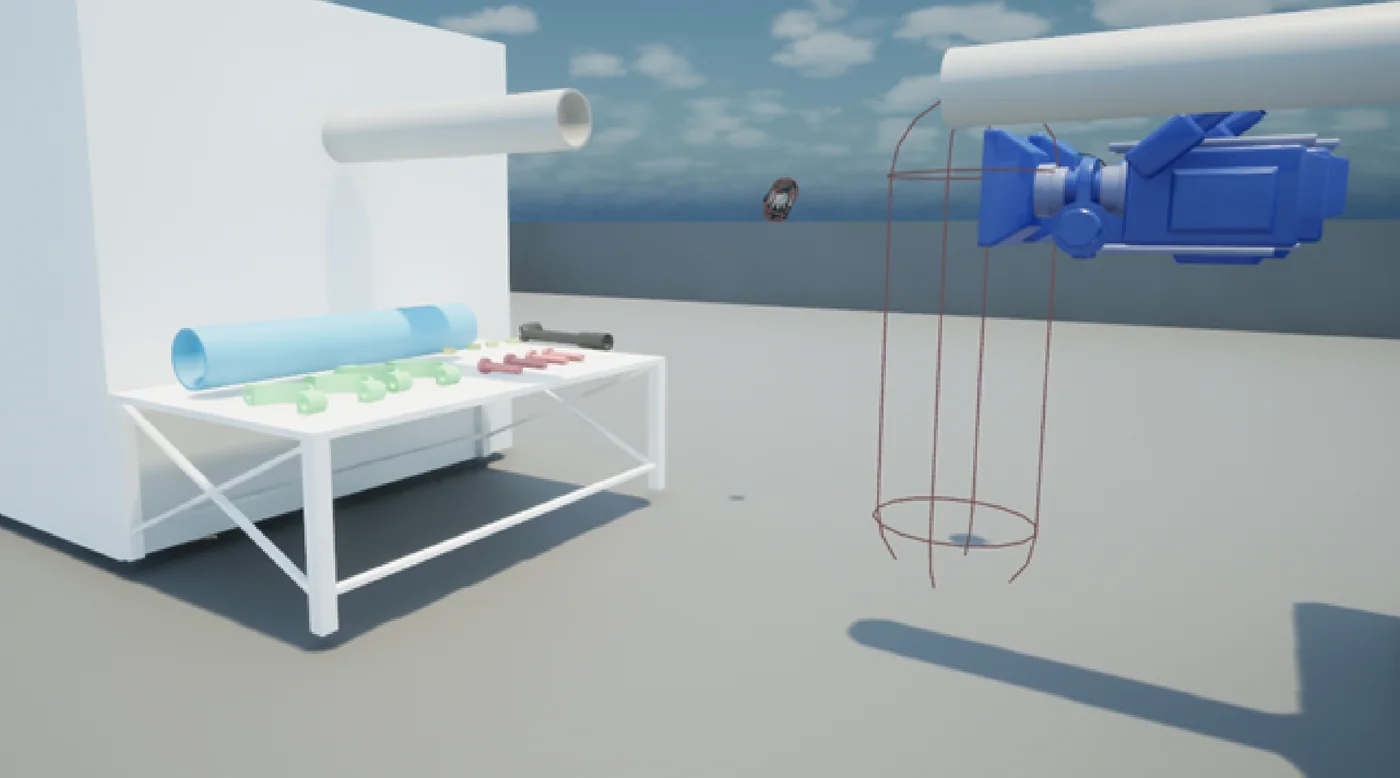
Each guide answers one question from the learner, and only one. All of them are created at run time, from the part itself: nothing is placed by hand.
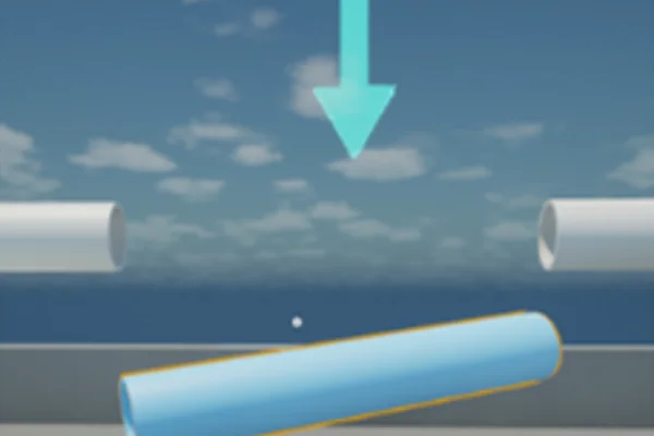 Indicator arrowWhich part?Hanging above the part to pick up, always facing the operator.
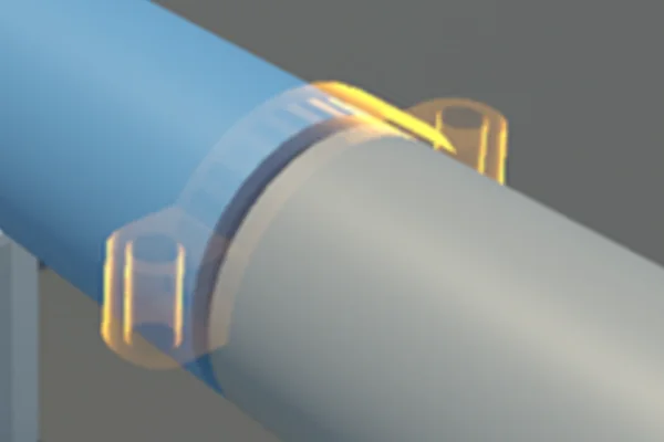 Target ghostWhere?Golden translucent copy of the part, at its final position.
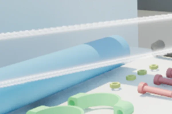 Animated ghostWhich way?White translucent copy that replays the path, from the real part to its target.
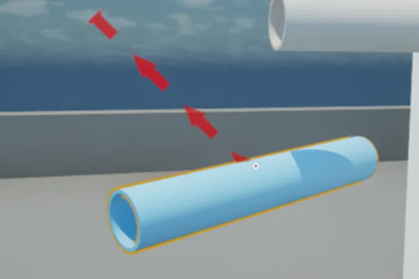 Arrowed pathWhich part goes where?Arrowed curve linking each part to its destination.
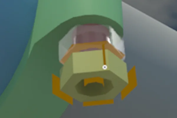 Joint ghostAnd now, which gesture?Once the part is snapped on, it shows the end of travel of the motion still to be made.
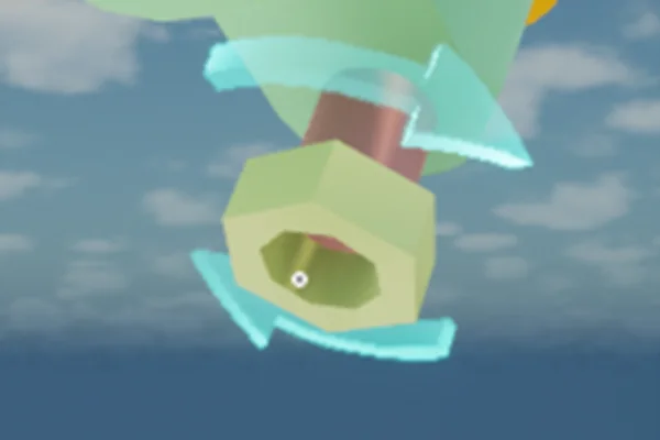 Joint arrowsIn which direction?Specific to each joint, turquoise blue, they show the motion allowed.
Screenshots of the demonstration scene.
- Six families, no more: too many cues on screen degrade learning.
- One colour per family, to tell them apart at a glance. Everything is translucent: suggest the motion without hiding the parts.
- No fixed size: ghosts are the size of the part, joint arrows are sized from its bounding volume. A part ten times larger needs no adjustment.
- A part made of several elements is rebuilt whole, without its collision volumes.
The guidance follows the assembly
Each location to fill goes through five states, and the guidance changes with them.
- Inactive
- Searching for a part
- Snapping
- Constrained motion
- Part in place

- Searching: the location spots a compatible, available part. Indicator arrow, target ghost, animated ghost and path appear.
- Snapping: the part enters the trigger zone, the physical joint is created.
- Constrained motion: only the remaining degree of freedom is simulated. The joint ghost and arrows take over.
- Part in place: the limit is reached, the step is validated, every guide disappears.
Seven mechanical joints
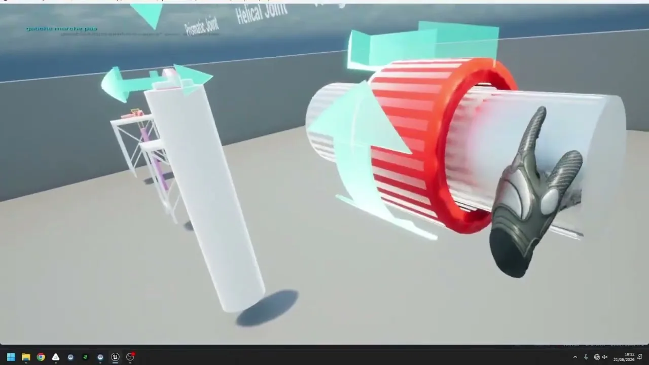
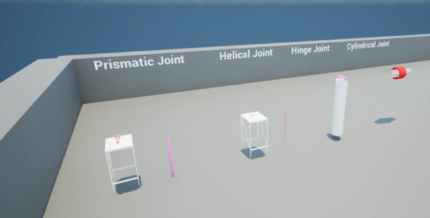
Seven joints are supported: fixed, prismatic, hinge, helical, cylindrical, ball and free. Once the part is snapped on, the guidance shows the motion the joint still allows: a translation, a rotation, or both coupled, as for a screw.
The arrows are never placed by hand: position, size and orientation are computed at run time from just two pieces of data, the part’s bounding volume and the joint’s declared axis.
When the operator gets it wrong
A scenario is not a strict sequence of steps: the learner can make mistakes, and should not have to start over for that.
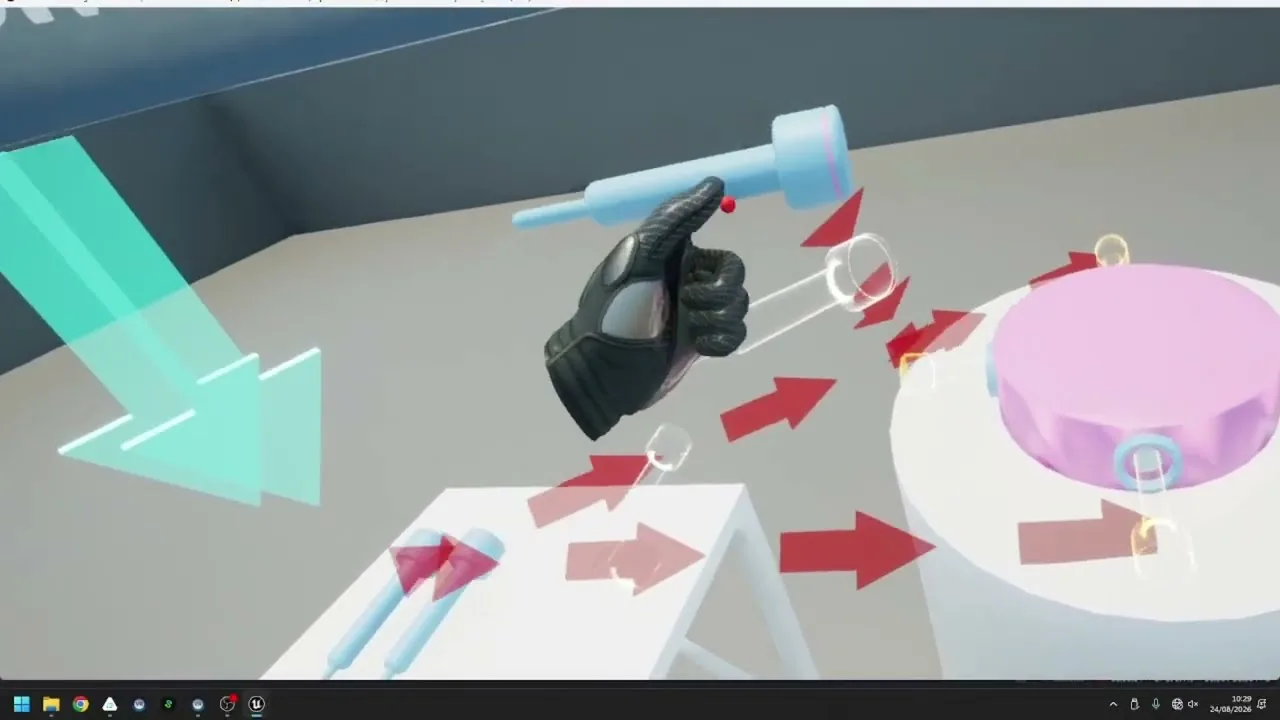
- Five identical screws for five holes: each location reserves its part, so the guides do not all converge on the same spot.
- A location taken by another part: the part left aside is reassigned at once. The operator simply sees their guidance point elsewhere.
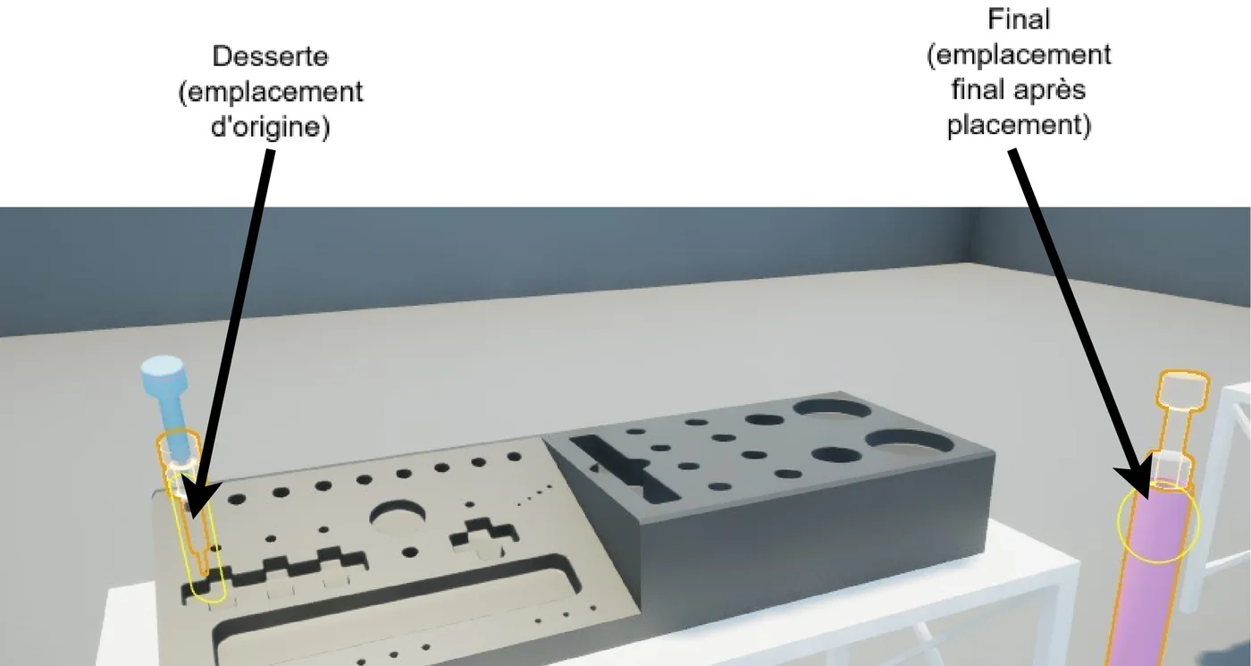
- A part already mounted at the start, to be moved: a transit location never seals, a destination location always does.
- A part put back on the wrong stand is still expected at its true destination.
- A part can be removed and then reassigned, if the scenario allows it.
Two modes, one control panel
Virtual reality is the intended use; a desktop mode, with keyboard and mouse, runs the same scenario without a headset. One key switches between the two, on the same code base.
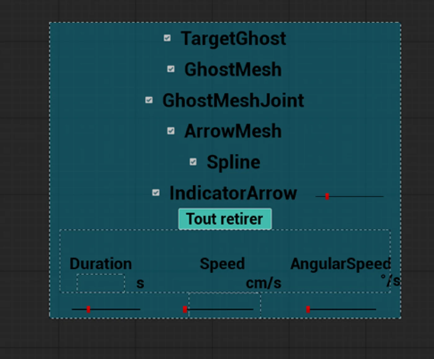
In the scene, an interactive panel lets the operator or the trainer tune the guidance:
- show or hide each family of guides, or all of them at once;
- set the duration, speed and angular speed of the animated ghost: the slowest constraint wins.
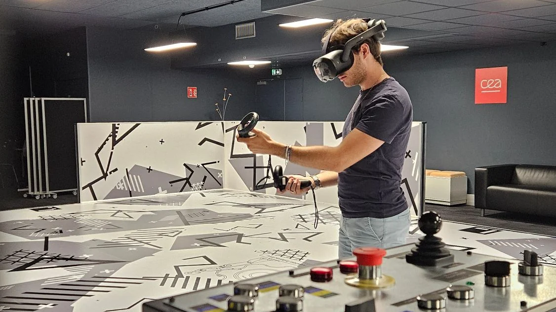
Headset trials (PICO 4 Ultra Enterprise, HTC Vive Focus 3) in the laboratory’s dedicated virtual reality room.
Approach
- Take over an existing code base of several thousand lines, specific to the laboratory: reproduce the reference scenarios, find the entry points, change things to understand them.
- Progress by elimination: a hypothesis, a trial, a note in the logbook.
- Test beyond the scenario: put a part in the wrong place and see what breaks. That is how reassignment came about.
- Plan for the general case: the prismatic joint’s arrows were designed from the start for every axis and every joint.
- Work the Agile way, in small steps: each addition is verified, demonstrated, then merged into the laboratory’s repository.
Results
- families of visual guides, generated at run time
- 6
- types of mechanical joint supported
- 7
- configurations validated: editor and packaged build, in VR and in desktop mode
- 4
- of technical documentation, approved and shared across the laboratory
- 35 pages
The laboratory now has a guidance module that can be adjusted without writing code, up-to-date demonstration scenes and complete documentation, all reusable for its next projects.
The work was also ported to a real project of the laboratory.